Sensor-Payload Rocket
My first full engineering lifecycle: design, build, integrate, defend at two reviews, launch, and then explain why the flight didn't land where the model said it would.
01 / OVERVIEW
Design, build, fly, explain
ENGR 100's Rocket Science section is Michigan's first-year design course built around a model rocket that carries its own sensor payload. Working as a small team, we designed the rocket and payload, built and integrated it, and launched it, then pulled the flight data off the payload and analyzed it in MATLAB.
Along the way the design had to pass two formal gates. At the Preliminary Design Review we defended the concept and the predicted performance. At the Flight Readiness Review we showed the built vehicle matched the design and was safe to fly.
- Preliminary Design ReviewDefending the concept, the payload plan, and the predicted performance before building.
- Flight Readiness ReviewShowing the built and integrated rocket was ready and safe to fly.
- Launch and dataSensor data recovered from the payload and compared against the simulation.
- Root cause analysisA written analysis of why the landing point differed from the prediction.
02 / SIMULATION
A three-phase flight model in Python
Before building anything, I wrote a flight simulation to predict how high the rocket would go. It steps through the flight in 0.01 s increments with simple Euler integration, recomputing drag and net force each step, and changes models at each phase.
- Powered ascent20 N of thrust for 1.6 s, with mass dropping linearly from 211.5 g to 179.5 g as propellant burns.
- CoastThrust off, dry mass, body drag only (CD 0.5 on the frontal area) until vertical velocity reaches zero.
- Parachute descentDrag switches to the parachute (CD 1.5, 0.2 m²) until the rocket reaches the ground.
The model is one-dimensional: no wind, no weathercocking, constant average thrust, and an instantly open parachute. Those simplifications are fine for predicting apogee, and they are exactly what limits it for predicting where the rocket lands.
03 / PAYLOAD
Calibrating the sensors
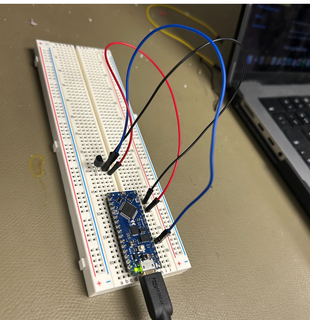
The payload electronics started on a breadboard. I wired an analog temperature sensor to an Arduino Nano and turned the raw readings into temperatures in two steps. The Arduino's 10-bit converter maps 0 to 5 V onto 0 to 1023, so the voltage is the raw value times 5/1023. A calibration line then converts voltage to temperature.
voltage       V = raw × 5 / 1023
calibration   T = 120.78 · V − 68.20   (°C)
inverse       V = (T + 68.20) / 120.78
04 / ROOT CAUSE
When the flight didn't match the model
The rocket flew, but it landed somewhere other than where the simulation predicted. Instead of shrugging it off, I went back to the recovered flight data and compiled a root cause analysis of why the landing deviated from the prediction.
The lesson carried straight into my later work. A model is only as good as the assumptions you can name, and the useful habit is writing those assumptions down before the test so you know where to look after it. That's the same reasoning behind the test limitations section in my HIROTEC handoff and the placeholder-input notes on my MASA shock model.