MAAX Ultraviolet Imager Proof of Concept
A student team proving out an auroral UV camera concept on a weather balloon, run with model-based systems engineering. I'm the team's risk officer.
01 / MISSION
Imaging the aurora in ultraviolet
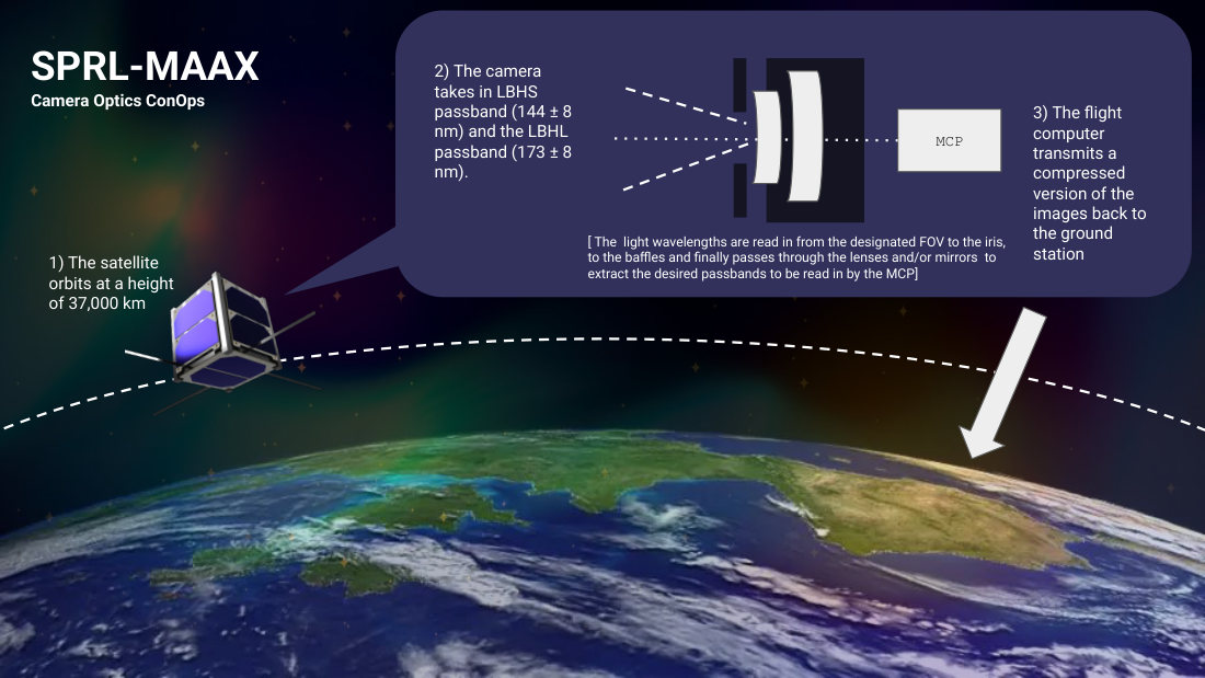
MAAX, the Magnetospheric Auroral Asymmetry eXplorer, is a NASA Heliophysics Small Explorer mission proposal led by the University of Michigan. Its MAAX Ultraviolet Imager (MUVI) would photograph the aurora in two far-ultraviolet bands to study how the northern and southern auroras differ.
Our team of 14 (a mix of AEROSP 388 students and upper-level 488 leads) is building a proof of concept for that imaging analysis. The flight demonstration is a CubeSat-style payload carried to about 90,000 ft by weather balloon, with a lens and filter system, avionics, and a camera. We brief MathWorks and SPRL stakeholders every two weeks and move through formal design reviews.
02 / REQUIREMENTS
A requirements model, not a document
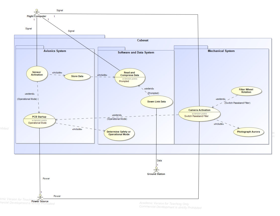
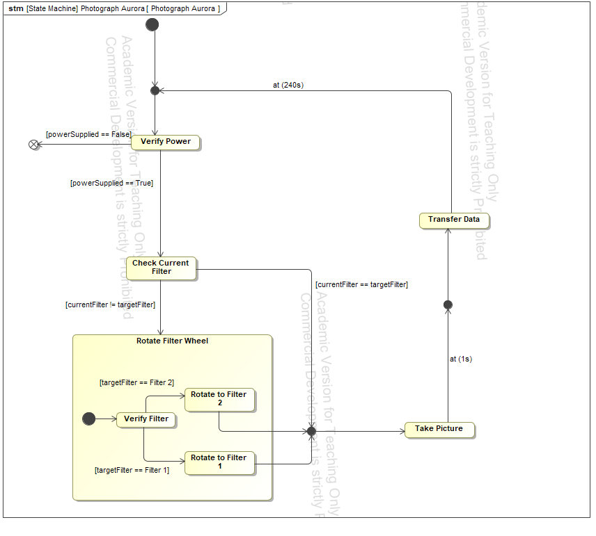
The project runs on model-based systems engineering. Instead of a requirements spreadsheet, the team keeps a SysML model in which every requirement is an element linked to where it came from and how it will be verified.
- L0 · CustomerWhat SPRL and MathWorks need: capture the auroral oval in both passbands, survive the balloon flight, and recover from an unexpected power loss.
- L1 · SystemDerived system requirements for resolution, temporal cadence, operating temperatures, mass, and data downlink.
- L2 · SubsystemSeparate requirement trees for avionics, software and data, and mechanical, each traced to the L1 requirements it supports.
- L3 · ComponentRequirements on specific parts such as the filter wheel, lenses, transmitter, and flight computer, each with a verification method: test, inspection, analysis, or demonstration.
03 / RISK
Running risk for a 14-person team
As risk officer I lead the team's risk management strategy and the failure mode and effects analysis (FMEA). Each risk is scored from 1 to 5 on severity, probability, and detectability, and the product is its risk priority number:
RPN = Severity × Probability × Detectability     (each 1–5, max 125)

RPN ≤ 30     acceptable · signed off by the risk officer
31 – 75      mitigate   · sub-team leads or risk officer
RPN > 75     critical   · chief technical engineer, chief of systems, or chief of operations
The strategy also defines who owns what. The chief of systems signs off on integration and communication risks, the chief of operations on cost and schedule, the chief technical engineer on safety and technical risks, and I can close any non-critical risk. Severity scores are tied to dollar ranges so a "major" failure means the same thing to every sub-team.
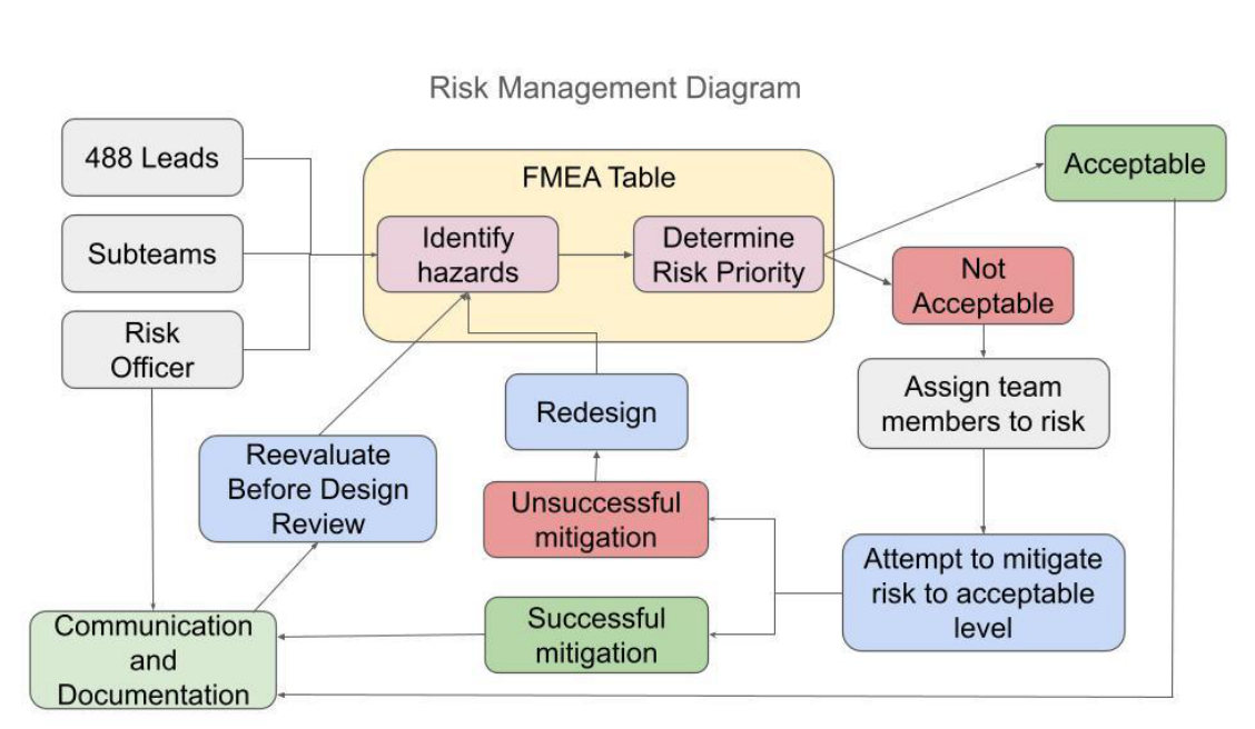
The two critical risks were not exotic hardware failures. SYS.06: cold at altitude could defocus the camera lens and clouds could fog the optics, producing footage nobody can use, and we wouldn't know until the payload was recovered. SYS.07: repeated testing could quietly degrade the UV components before flight. Both scored high mainly because they're hard to detect, which points mitigation toward thermal testing at flight temperatures and toward knowing each component's limits before it goes into a test setup.
The plan re-scores every risk before and after each review. RPNs are expected to drop through PDR and CDR as designs and mitigations firm up, with the goal of every risk under 30 by the flight readiness review. A burn-down chart tracks the total by subsystem. The strategy was signed off by the full team on September 28, 2026.
04 / NEXT
Toward the balloon flight
The objectives and requirements have been carried through several design reviews to a baseline. On the avionics side I'm now integrating the lens architecture, avionics, and camera for the weather balloon flight to 90,000 ft. This page will grow as the project reaches PDR, CDR, and flight.