Flexible Robotic End Effector
A three-finger, six-motor gripper whose fingers are pulled by tendons, built to pick up 5 to 20 kg automotive parts without a custom tool for every shape.
01 / PROBLEM
One tool per part doesn't scale
HIROTEC is a Tier 1 supplier of body-in-white tooling and automation. Its robots move stamped panels, brackets, and assemblies, and almost every new part shape gets its own end-of-arm tool. That costs design hours and fixture budget every time a program changes.
I proposed a gripper that adapts instead: fingers that wrap around whatever they're given, sized for parts from 5 to 20 kg. I pitched it, secured $11,200 in funding, and ran it as the sole project champion from requirements through verification, directing a fellow intern, Noah Ericson, along the way.
02 / CONCEPT
Borrowing from the human hand
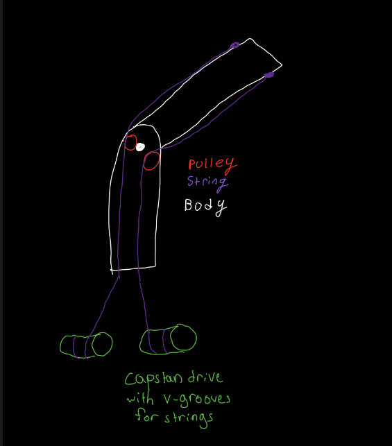
Human fingers have no motors in them. Muscles in the forearm pull flexor tendons, and small ring-shaped annular pulleys keep those tendons close to the bone so the pull turns into torque at each joint. The gripper copies that layout: the motors stay in the base, and Bowden cables carry the pull up to the fingers.
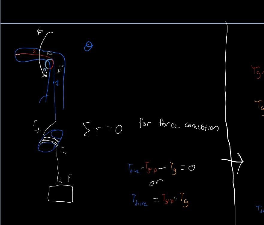
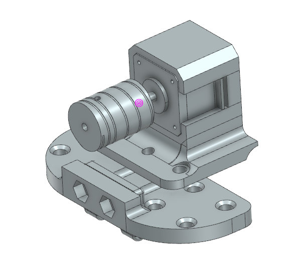
At the motor end, each tendon wraps a capstan drum turned by an Arduino-controlled NEMA 17 stepper. By the capstan equation, holding force grows exponentially with the number of wraps, so a small motor can hold a heavy load. The tradeoff is that more wraps put more stress on the line.
03 / DESIGN
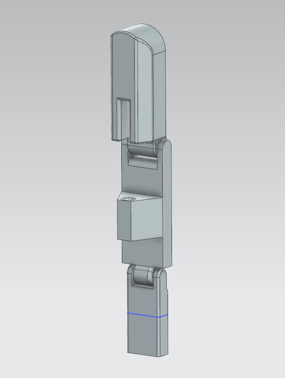
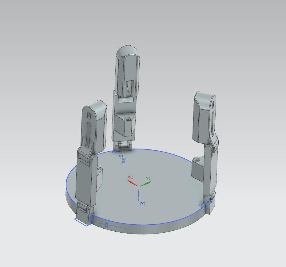
Three fingers, six motors, two joints each
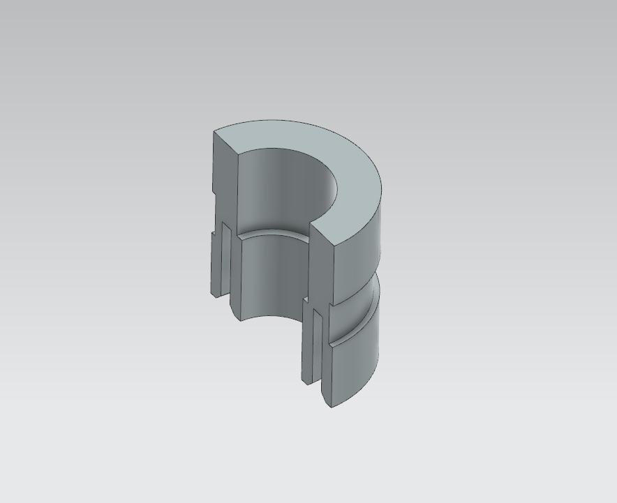
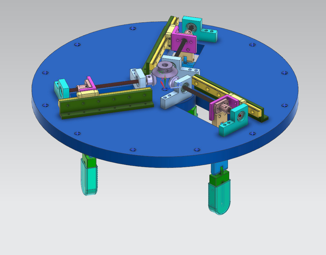
I modeled the gripper in Siemens NX and built the capstan drums as parametric models in CadQuery (Python), so drum diameter and groove count could change without redrawing. For each finger I derived fingertip kinematics and per-joint gravity torques using homogeneous transforms and rotation matrices.
- Two joints per fingerMore joints add flexibility but split the tendon force across more load paths. Two joints gave the best balance.
- Antagonistic pairsA tendon on each side holds the finger stiff in both directions. With a single tendon, the finger springs back the moment the load comes off.
- Capstan driveHigh holding force from a small stepper. The catch is line wear, which made the choice of material important.
- Radial railsFor the third phase, each finger rides a lead-screw rail so the grip can open or close around different part sizes.
04 / PROTOTYPE
Print it, pull on it, find out
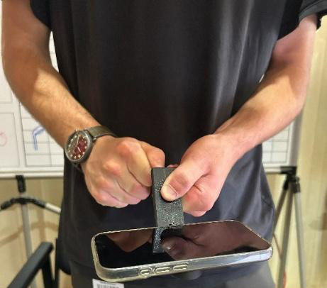
The first printed finger (Rev 1) could lift a phone when we pulled on its line by hand, and it showed us two things. Fluorocarbon line stretched under load, so we switched to braided line. More importantly, the line crossed the joint almost in line with the finger, so most of the pull went straight through the finger instead of turning it.
The torque depends on how far the line sits from the joint where it crosses it. That one finding drove every revision after Rev 1.
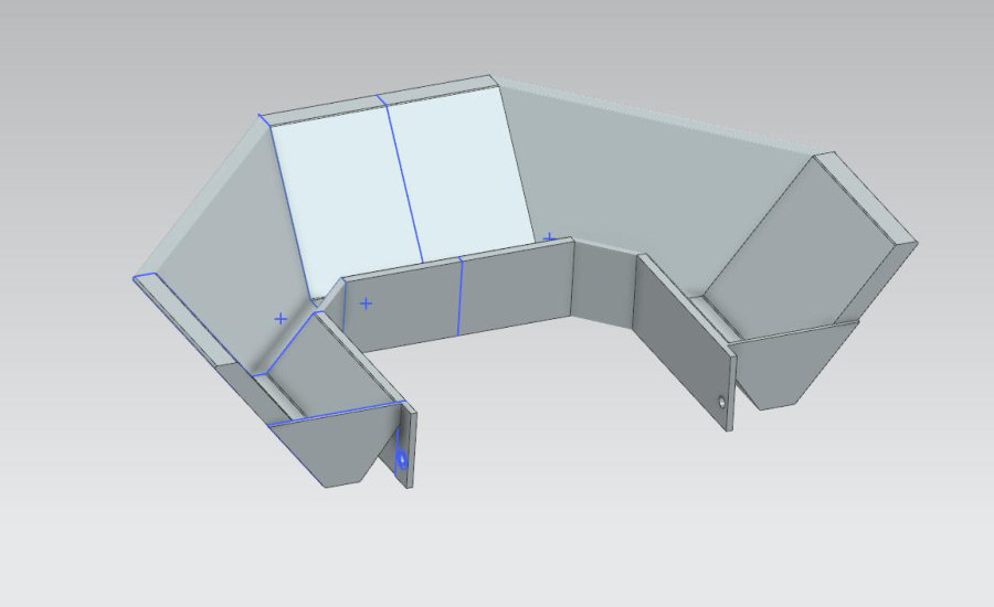
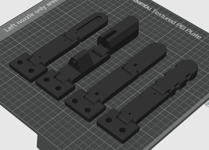
From there we printed four finger designs to compare routing strategies head to head. Rev 2 moved the joint down and hollowed out the finger for a better pull angle. Rev 3 wrapped the line around the joint itself. Rev 4 kept the line inside the finger, running along both sides and around the tip, so it would never touch the part being gripped.
05 / VERIFICATION
A load cell settles the argument
I wrote a three-stage verification plan: fingertip force at a load cell, then friction coefficient, then static payload. For the first stage, each finger hung under an inverted Loadstar load cell. A NEMA 17 stepper on an A4988 driver wound the line onto a 31.25 mm capstan, curling the finger up into the cell. A Python script logged force to CSV and a MATLAB script turned each run into a force-time plot.
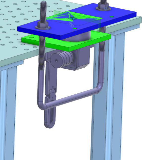
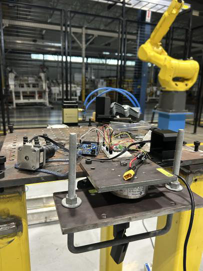
Rev 2 hit the highest peak at 2.4 N, but it slid off the load cell and can't apply force outward. Rev 1 with looped routing reached 1.4 N and works in both directions, so it became the recommended baseline. The handoff report also lists what the test can't tell you yet: single runs, friction in printed joints, and line stretch. It recommends at least three repeats per configuration before anyone relies on the numbers.
06 / OUTCOME
Handed off early and under budget
I briefed HIROTEC executives on the design, which compared well against a multi-month effort by the parent company's team in Japan, then wrote a formal handoff package: design rationale, test procedure and code, raw data, and next steps for the friction and payload phases.
Along the way I also flagged process gaps in weld verification and robot programming. The fixes I proposed are projected to cut verification time by up to 50% and to stop errors that kept coming back because of missing documentation.
Also at HIROTEC
Shop-floor fixes
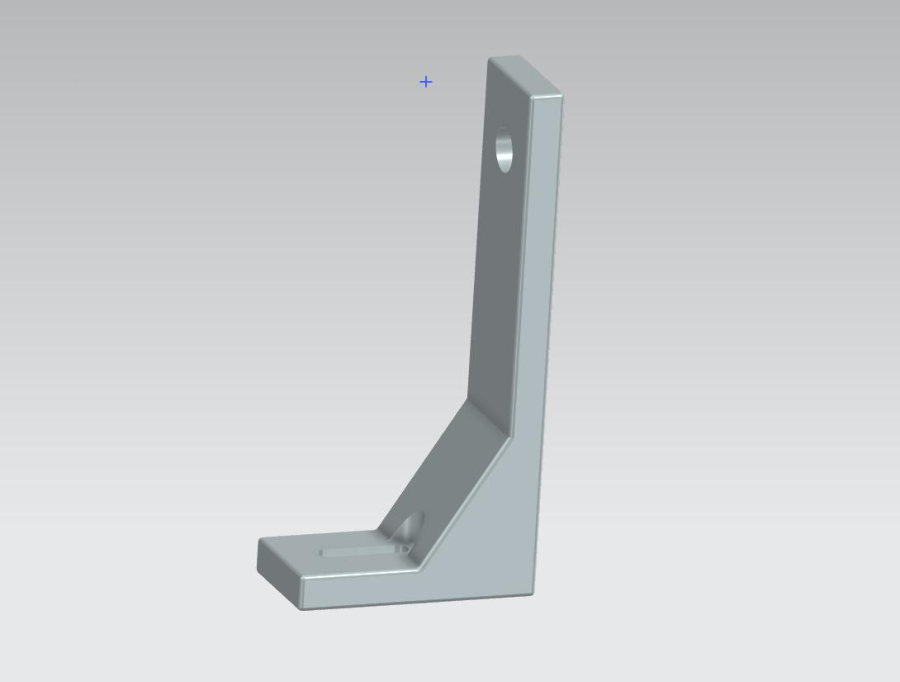
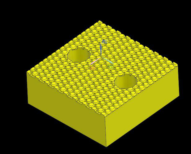
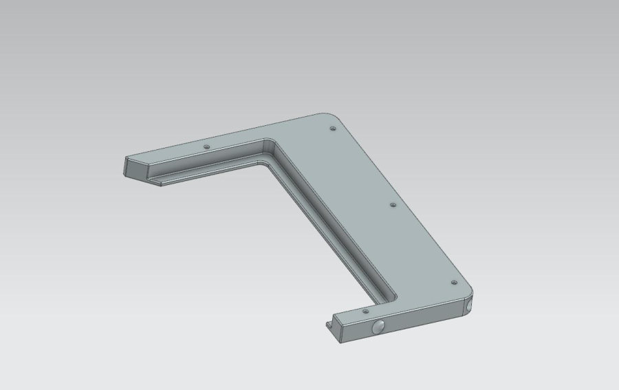
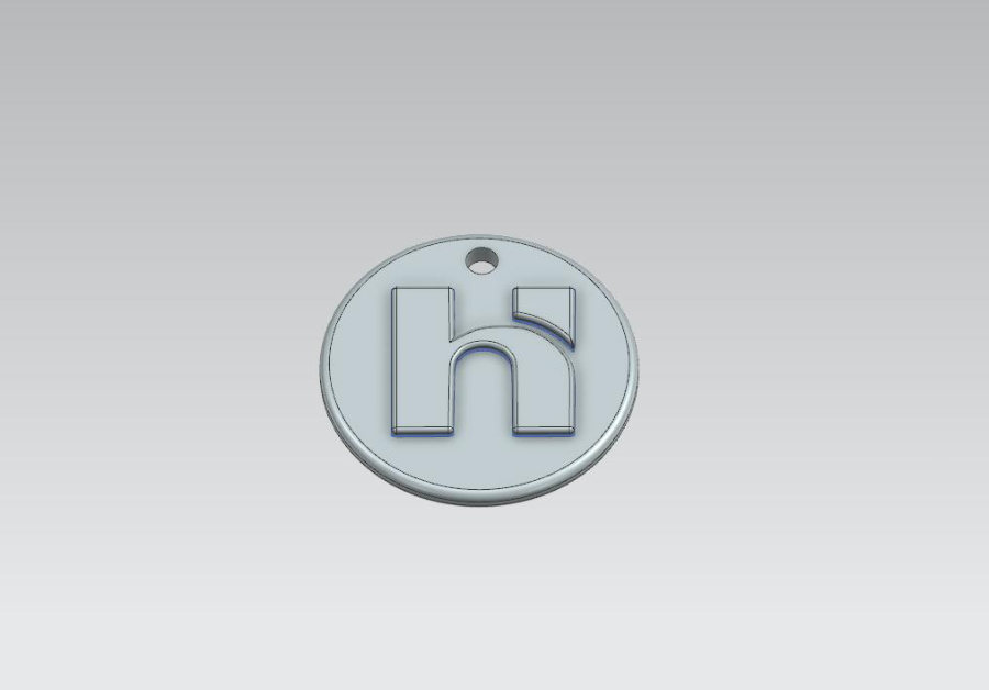
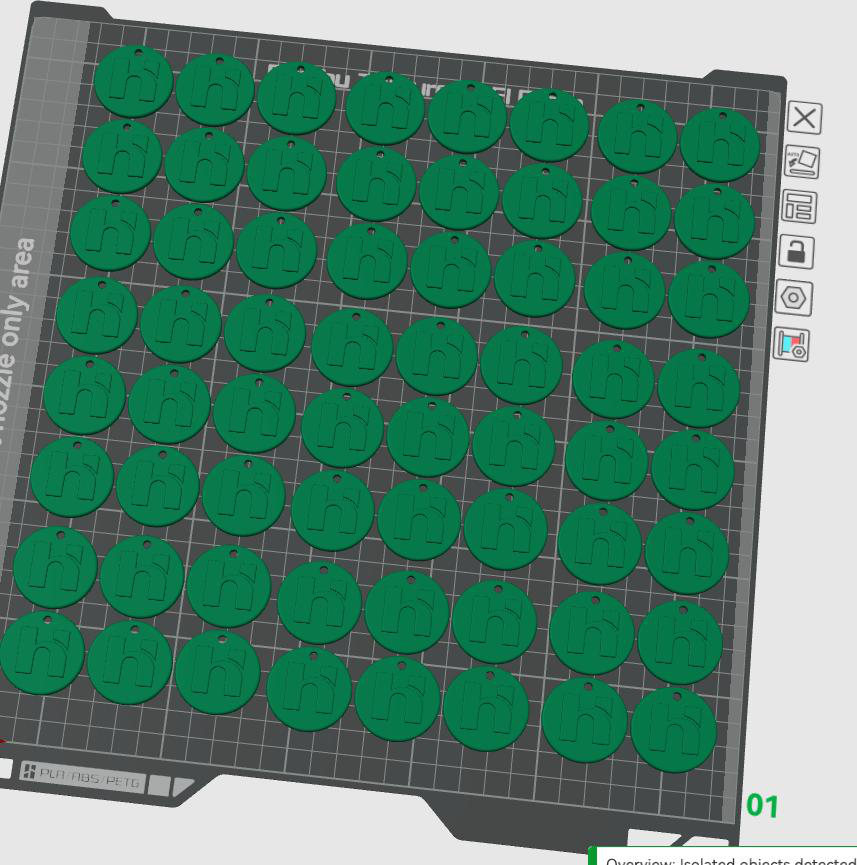
Smaller parts I designed in NX and printed for the production floor, most of which went into daily use.