SAE Aero Design Aerodynamics
Aerodynamic analysis for a student competition aircraft: from a first vortex-lattice wing to a full-configuration model and a takeoff-performance simulation.
01 / CONTEXT
Aero for a competition airplane
M-Fly designs and builds radio-controlled aircraft for the SAE Aero Design competition, where teams are scored on how well their aircraft meets a mission under tight size, power, and takeoff constraints. The aerodynamics sub-team owns the wing and tail sizing, airfoil choices, and the performance predictions the rest of the design depends on.
My work ran from airfoil and wing analysis to full-aircraft models that checked the design against critical flight parameters and drag targets. The changes that came out of it shortened takeoff time by 20%.
02 / VORTEX LATTICE
Learning AVL on a single wing
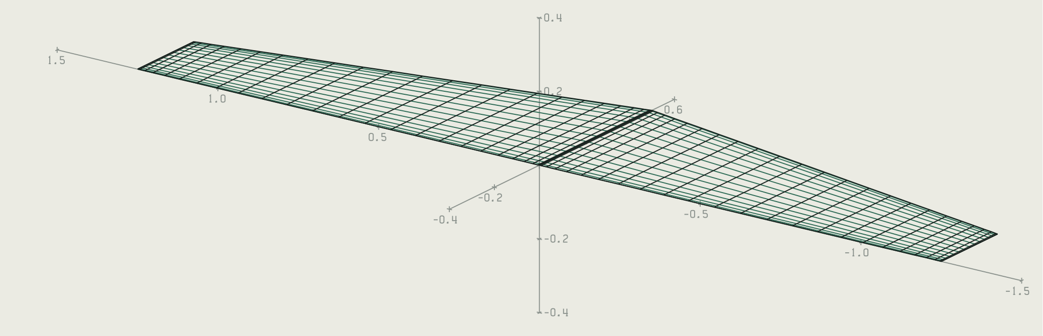
AVL (Athena Vortex Lattice) models lifting surfaces as a lattice of horseshoe vortices and solves for lift distribution, induced drag, and stability derivatives in seconds. I started with a single tapered wing to learn the tool: a 2.5 m span, 0.5 m root chord tapering to 0.25 m, with a NACA 4412 section, discretized into 16 chordwise by 24 spanwise panels per side.
03 / FULL CONFIGURATION
The whole airplane in one model
From there I built a full-configuration AVL model of a candidate aircraft, YMX-11: a tapered main wing on a NACA 4412 section, a horizontal and vertical tail on NACA 0012, and the fuselage modeled as crossed flat plates so its lift and side force show up in the stability results.
The same model sized the control surfaces. With the elevator hinge at 40% of the tail chord, the aircraft reaches a 130°/s pitch rate at 11 degrees of elevator. With ailerons on the rear third of the wing chord, it reaches a 130°/s roll rate at 14 degrees of deflection.
- Main wing span3.65 m
- Wing chord0.50 → 0.25 m
- Horizontal tail0.87 × 0.17 m
- Vertical tail height0.68 m
- Pitch rate, 11.0° elevator130°/s
- Roll rate, 14.1° aileron130°/s
04 / AIRFOILS & CFD
Choosing the section, then checking it
Airfoil choice drives how much lift the wing makes at low takeoff speeds. I compared candidate sections in XFLR5, including the NACA 4412, Eppler E71, Wortmann FX 71-L-150/30, and Göttingen 121, before carrying the NACA 4412 forward into AVL.
AVL is fast but inviscid, so it can't predict viscous drag or stall. For those, the design was checked in STAR-CCM+ against the drag coefficients and flight parameters it needed to hit, and the results drove the iterative changes that followed.
05 / TAKEOFF
Modeling the ground roll
Takeoff is where SAE aircraft are most constrained, so I wrote a MATLAB model of the ground roll. Each 0.1 s step it computes lift and drag at the current speed, reduces wheel friction as lift unloads the wheels, and uses a speed-dependent thrust curve for the propeller, which loses thrust as the aircraft speeds up.
thrust     T(v) = 50.9 − v − 0.0344·v²     (N)
lift/drag  L, D = ½ ρ v² S · (C_L, C_D)
friction   F_f = μ · max(0, W − L)
accel      a = (T − D − F_f) / m           until v = 11.2 m/s
- Mass14.97 kg
- Wing area1.57 m²
- CL / CD on the ground1.36 / 0.29
- Rolling friction μ0.0275